
This is a very large topic and I recommend to search for more content about mesh topology on World Wide Web and social media. It’s also about personal preferences and performance when it comes to assets made for game engines. In some cases, there’s a dependency/relationship between topology and assigned materials, especially when it comes to UV mapping and use of texture maps.
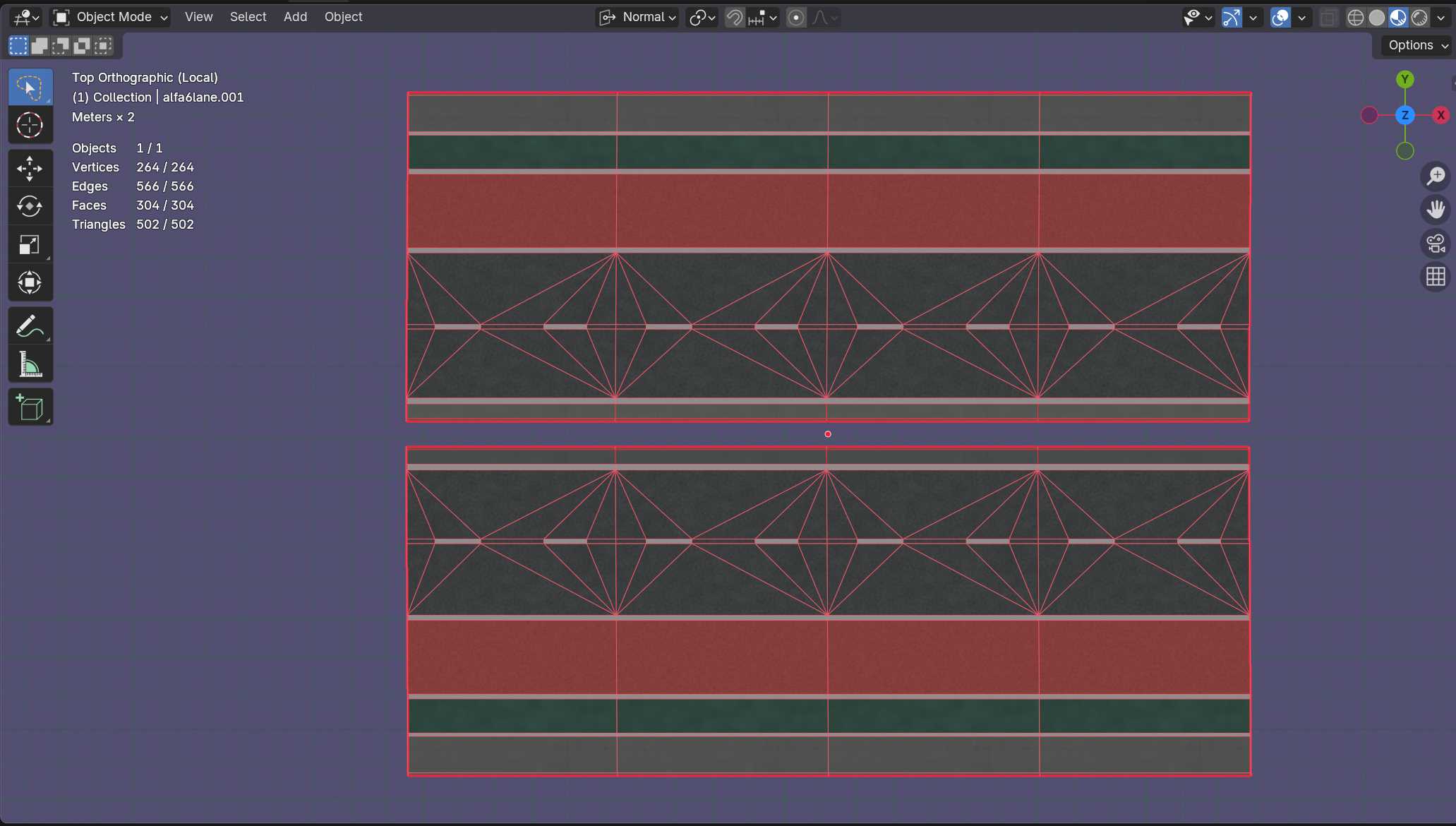
If we look at the topology in the image, we see something that is obviously a street with several lanes. This mesh is textured with five different surface materials, where the material is assigned to faces between the red lines. Such lines are known as edges. Between each line there’s a face.
The face has a diagonal line that usually isn’t visible unless we triangulate selected faces.
In Blender we can also activate some stats that is displayed for the selected mesh object. The stats in the image above shows the following data:
- Objects: 1/1 – number of selected objects
- Vertices: 264/264 – total number of vertex points
- Edges: 566/566 – total number of edges
- Faces: 304/304 – total number of faces
- Triangles: 502/502 – total number of triangles (faces with diagonals)
The last one (triangles) is the one we should pay attention to when optimizing mesh objects for use in game engines. In this case this mesh alone is considered to be low poly – see https://en.wikipedia.org/wiki/Low_poly
Topology
The topology is mainly the overall mesh structure of a 3D object that later on is to be exported to be used as an asset inside a game engine. It’s important to have a topology that is optimized and clean, where all the edges are connected to each other without edge/face/vertex overlaps, since these can affect the shading, and also the UVs.
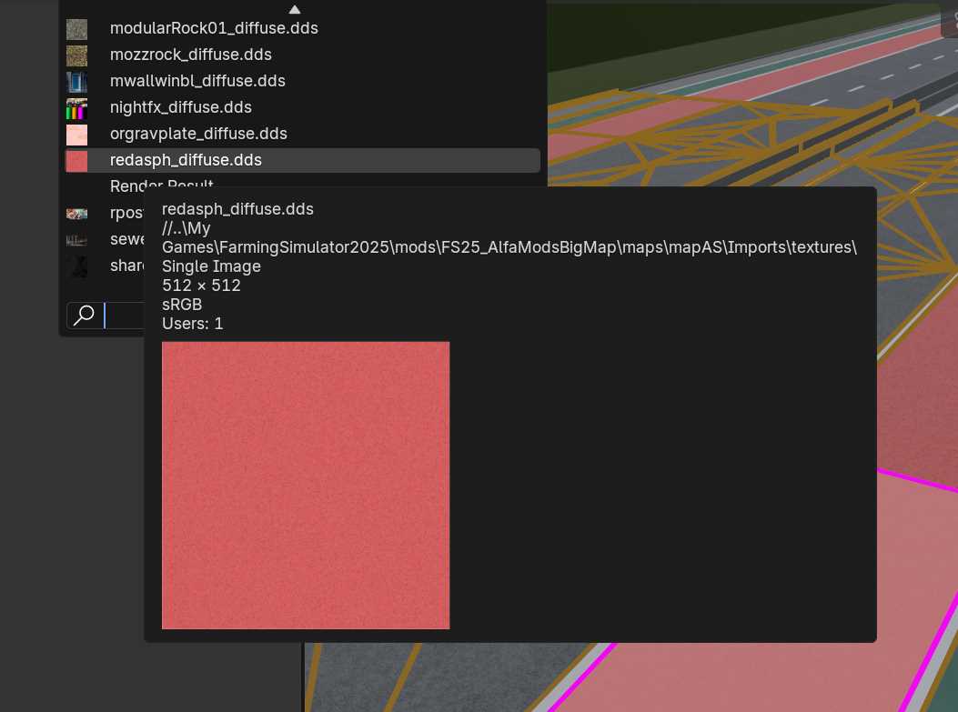
In some cases we can also triangulate faces to make it easier for the game engine to read the mesh topology. When exporting to other file formats, we can also triangulate faces (see image below).
UV Mapping and Topology
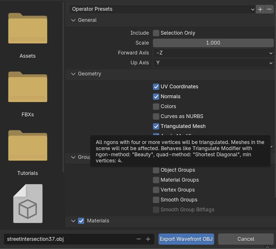
If we look at the UVs for some selected faces in Blender, we’ll see that the faces aren’t covering the whole texture. This isn’t necessarily a bad thing, since the texture would look stretched when faces are rectangular and not quadratic.
On the other side, we could subdivide the faces to get quadratic faces. We could also scale up the selected face(s) inside the Blender’s UV Editor (left side of the image) to make the face cover more of the texture.
However, this is a seamless noise texture, and the noise (small darker dots) would become smaller.
If we are going to apply normal maps or other fancy maps to the material inside a game engine, we could adjust the topology or the other texture maps, or by adjusting the UVs.
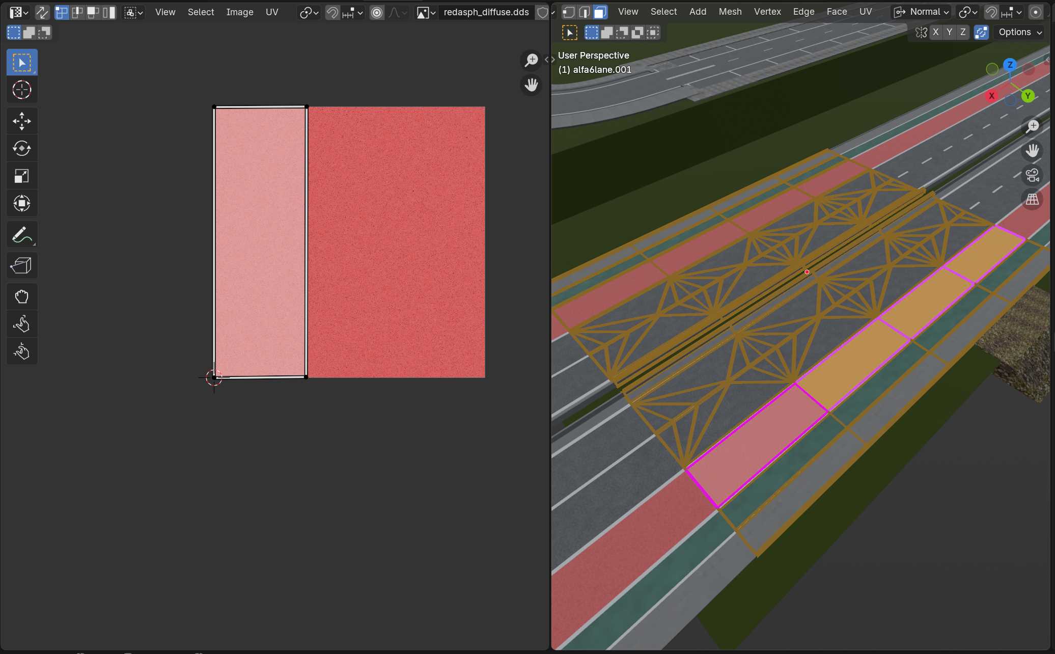
Why the texture to the left is quadratic, is mainly because of the power of two, meaning 512 x 512 pixels.
Triangulating Faces
To change the mesh topology, we can move into Edit Mode and then Vertex Mode, using the shortkeys 1, 2 or 3 on the keyboard (not NumPad). Next, we can select two vertex points and hit the J-key to join.
Before joining, we need to be absolute sure that the two vertices isn’t lose, and that all edges are connected to the vertices.
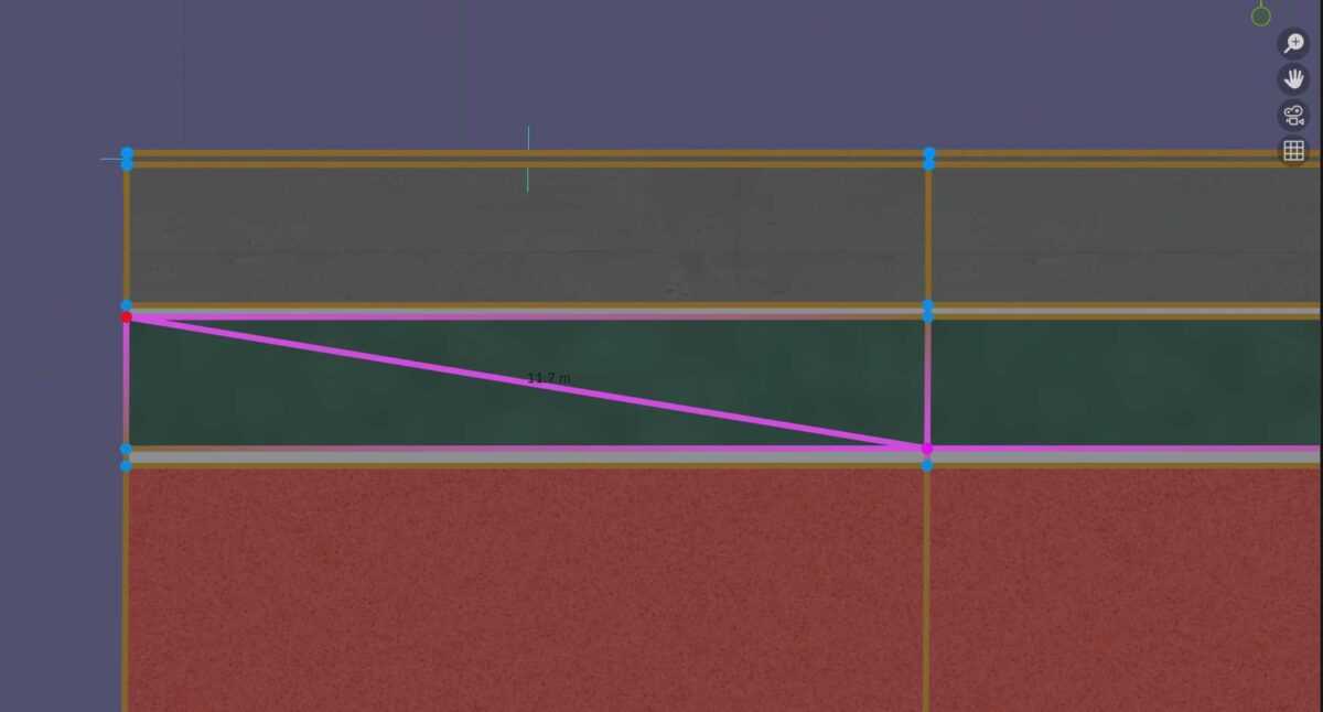
Now we have a new diagonal edge between the two pink vertices. This is how we manually can triangulate the faces.
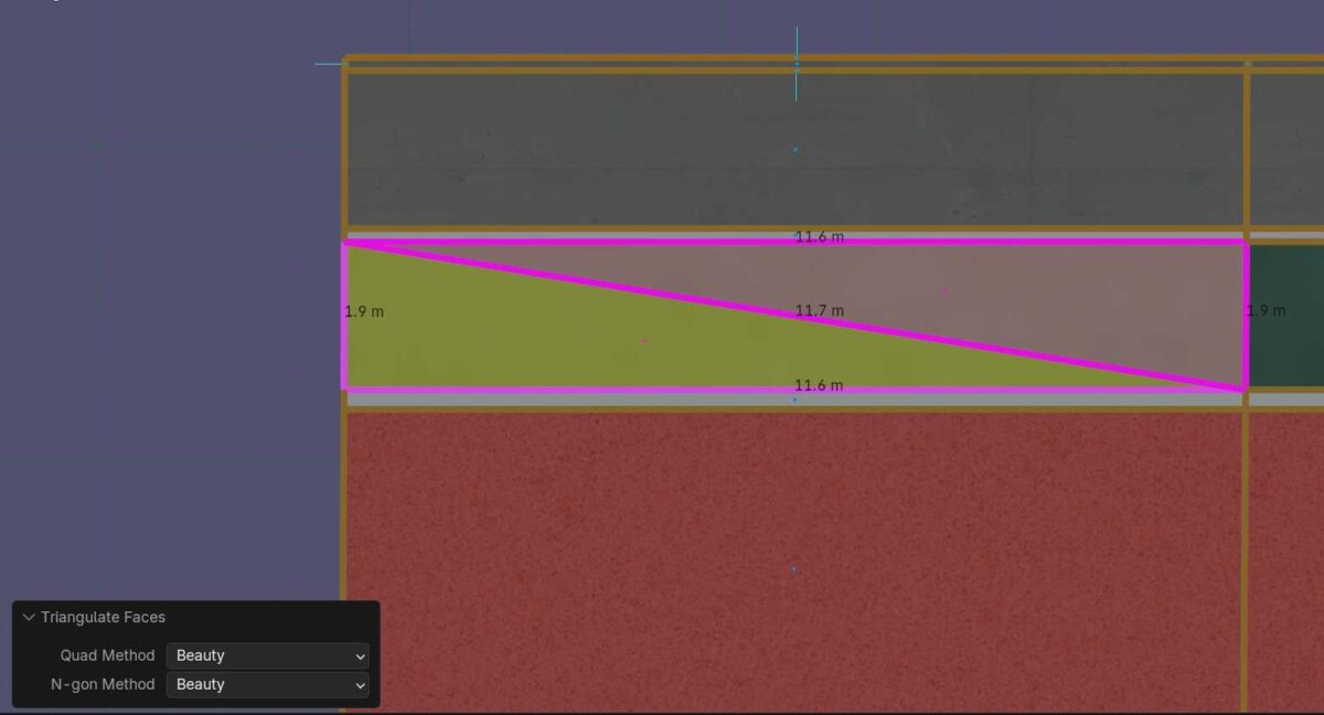
The other method is to select a face by first switching to Face Mode, and then hit the CTRL + T, and we get the same result.
Another alternative method, is to use the triangulate modifier. But this is a modifier that will triangulate all faces in a mesh object. And as usual, most modifiers inside Blender can be assigned when we are in Object Mode.
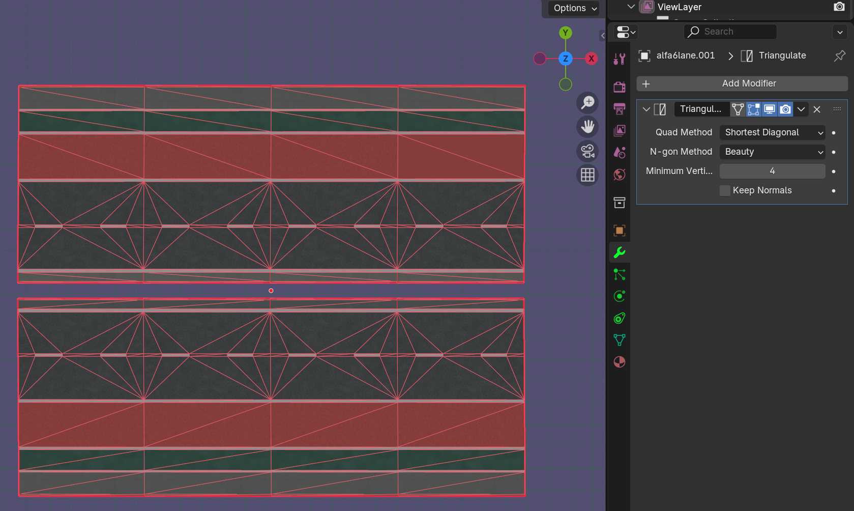
And we can now apply the modifier if necessary.
This modifier also makes the diagonal edges visible when not applied when we move back to Edit Mode. This can be useful when we want to see the triangles when manipulating a mesh object.