
2D View – Top to Bottom View – Object Mode
- Select the cube by left-clicking the object inside the active viewport.
- Press X (shortkey) on the keyboard to delete the cube or from the pop-up that asks if you want to delete selected objects.
- Press SHIFT + A to open up the Add Menu and pick Plane from the Mesh sub-menu.
- Press 7 on the NumPad to activate the top-down viewport. You may also press 5 to go from perspective to orthographic view.
- In this view, you can use your scroll wheel to zoom in and out by rolling it forward and backward.
- In this view, you can also hold down the SHIFT key on your keyboard and simultaneously press the middle mouse button to pan in any direction inside the viewport.
- Alternatively, you can use the viewport buttons located below the green, blue, or red cross in the top-right corner of the viewport. You can also click directly on the blue Z, red X or green Y in the cross to switch fast to other views.
- You can also use the shortcut keys G to move, S to scale, and R to rotate the Plane, just to quickly see what these keys do. Press CTRL + Z to undo these operations and return the Plane to its original state.
Edit Mode
- Press the TAB key to enter Edit Mode with the Plane selected. This is the active mode we use when we want to work on each individual or several surfaces (faces), edges, or vertex points of a 3D mesh, such as the plane primitive.
- Alternatively, you can click outside the selected object (the Plane primitive) to deselect it.
- Press the 1 key on your keyboard (not the NumPad) to switch to vertex point mode, or click the first button next to ‘ Edit Mode’. There are three buttons with cubes, where the first one is for vertex mode, the second one is for edge mode, and the third is for face mode. The shortcut keys for the last two are 2 and 3.
- Left-click on the first vertex in the top-left corner of the Plane to select it.
- Left-click on the next vertex in the top-right corner to select it, and Blender will automatically deselect the previously selected one.
- Hold down the SHIFT key to select the vertex in the top-left corner, which will select both vertex points, and release the SHIFT key. By default, the selected points are displayed in orange, and the recently selected points are shown in white.
- Left-click outside the Plane in the ‘grey space’ to deselect the points. Then, left-click in the ‘grey space’ and drag the mouse to create a selection window that encompasses all four vertex points of the Plane.
- Left-click outside the Plane again to deselect the points.
Deleting vertex and extruding vertex
- Select the first vertex point again in the upper-left corner of the Plane primitive.
- Press X on your keyboard to display the Delete Menu and select Vertices.
- The vertex is now deleted, but it will also remove the face and some of the edges to which the vertex is connected.
- Drag a selection window over the two other connected vertices on the right side of the Plane primitive, and then press X on your keyboard to bring up the Delete Menu.
- Select Vertices in the Delete Menu to delete the two vertices. We now have one vertex point left inside the viewport, which is represented by the small black dot (indicating it is not selected). This one is the one we will use to draw in 2D.
- Click on the remaining vertex point to select it.
- Press E on the keyboard for Extrude, and move your mouse away from you. You will see a colored line that is drawn between the old vertex and the new vertex.
- Left-click anywhere inside the ‘grey space’ to place the new vertex. This will finalise the extrusion. Between the two vertices, we now have a new edge line.
- By default, the new vertex appears selected, so we can press E again to extrude and place another vertex by moving our mouse and left-clicking to finalise the placement. You can repeat this as many times as you like, just for practice.
Moving vertex
- Press G (like G for grab) on the keyboard to move your last extruded vertex, and left-click to finalise.
- Undo all the extrude operations by pressing Ctrl+Z to revert to the single vertex point from which we extruded.
Direction locked extrusion and movement
- Select the vertex point again, and then press E + Y on your keyboard while moving your mouse. Left-click to finalise the placement of the new vertex.
- Press E + X and move your mouse to extrude in the X-direction, and finalise by left-clicking.
- Press G + X and move your mouse to move the active vertex in the X-direction. Finalise by left-clicking.
Each time we move a mesh/vertex/face/edge in Blender, a small window in the bottom left corner by default displays the distance moved in the XYZ direction. You can also change the value in that window to fix the placement if needed. - Alternatively, press E + X + 1 to extrude to a new vertex 1 meter away from the old one. Left-click to finalise.
This will give us a one-meter-long edge between the two vertices.
Blender Units Setup – Scene Properties
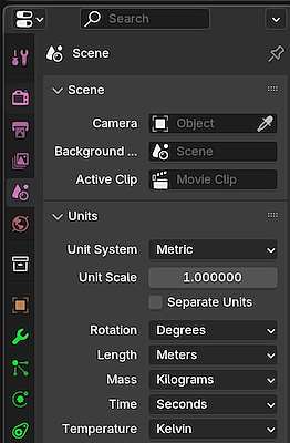
Scene Properties, a panel within the Properties Panel, located to the right of the viewport (by default), we find a section named Units. Depending on your Blender version, the message displayed may differ. If you expand that section by left-clicking on it, you will see that Blender uses metric as the default unit system.
To display units in a format other than meters, we can change the setting where it says ‘length’ and select centimeters from the drop-down, for example.
The imperial unit system is primarily a unit system used in the United States. You can just modify this section where it says ‘Unit System’, but please be careful if you plan to export your Blender content to game engines or create assets within Blender for your asset library. You may encounter issues where assets, objects, characters and even the entire scene are out of scale, particularly with architectural objects such as doors, doorways, and similar elements, especially when a playable character enters a building, opens a gate, or similar scenarios. This occurs when two entirely different unit systems are used between applications, such as game engines (E.g., Unreal Engine) or 3D/2D software applications.
Please ensure you are always aware of the unit system the game engine is using or has been configured for. The same applies to tools for converting or exporting to various file formats, such as Wavefront (.obj) and FBX (.fbx), among others. If you’re unsure about what you’re doing, it’s best to stick with the default unit system used by Blender for now.
Anyway, we’ll continue and follow the teacher’s lead for this practice.
- Set Units System to Imperial (this will change the background grid inside the viewport)
- Set Length to Inches.
- Select the last vertex we extruded and press E + X + 48, then press ENTER to finalise. You can type 48 on your NumPad. We have now extruded to a 48-inch long edge between the new and the previous vertex.
Snapping vertex
- At the top bar above the viewport, there is a magnet icon, also known as a horseshoe. Click on the icon to activate it (it will turn blue).
- Click the button next to the horseshoe to open the Snap Menu. If you hold your cursor over the buttons, you’ll see a small text that says ‘Snapping’.
- Select “Vertex” inside the Snapping Menu, and then move your cursor away from the menu; it will automatically close.
- Select the previously selected vertex and press G + X. Then, move your mouse so that the cursor is hovering over another vertex. You’ll see a colored square around the vertex you are hovering over. Left-click to finalise.
What happened here is that the vertex we moved ‘snaps’ horizontally (in the X-direction) to a position aligned with the vertex we hovered over.
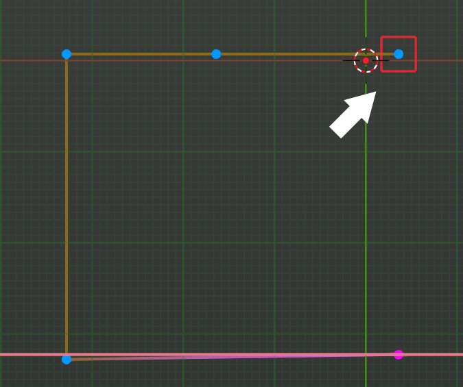
As you can see in the picture above, the selected vertex (in purple in my Blender) is positioning itself to roughly mirror the X-position of the vertex we hovered our cursor above, as indicated by this colored square. This is a tool used for precise alignment when working with 3D and 2D surfaces.
Filling between the vertices (create a new edge line)
- Drag a selection window around the two aligned vertices to make them both selected.
- Press F on the keyboard to Fill (create a new edge line between the vertices).
Filling between edges (create a new face/surface)
Filling can be done between two or more edges. It can also be done if we have an edge loop, meaning that edges connect all the vertices, and all we are missing is the face or surface itself. This can be done by:
- Drag a selection window around all the vertices (this will also select the edges automatically).
- Press F to fill between them all (creates a new face/surface), making this into what is primarily called a mesh.
Rectangle (face) within a rectangle – vertex slide
- Press 2 for edge mode on the keyboard
- Click on the top edge to select it (top edge of the plane inside the viewport). It will turn lit.
- Right-click and select Subdivide from the pop-up menu. If the small panel in the lower-left corner appears, simply leave it at Number of Cuts = 1.
- Go back to vertex mode (1) and select the newly created vertex. Then, hit G+G (quickly press G twice to slide the vertex slightly to the right and left.) Finally, left-click to finalise.
Notice that the small pop-up panel now reads ‘Vertex Slide’. You can fine-tune the slide by changing the value where it says Factor.
Extrude a vertex within a surface (rectangle) with snapping
- Press E + Y to extrude the vertex somewhat downwards to create a new vertex. As always, left-click to finalise.
- Go to the Snapping menu and select Edge.
- Select the new vertex point and press E + X while moving your cursor over to the edge to the right of the plane primitive, and finalise (left-click).
Connected geometry vs non-connected
In the video, the teacher will show us the difference between connected and non-connected geometry. If we move some of the vertices, but not the one we snapped to the edge, we see that the edges will follow the movement. But if we move the one we snapped, we’ll now know that it’s not connected to the edge, and therefore is ‘living a life on its own’. Yet, there are solutions for these types of relationship issues that occur in Blender. So here’s how we do that:
- Press 2 on the keyboard for edge mode.
- Click on the edge where the non-connected vertex is aligned.
- Right-click and select “Subdivide” from the list, keeping the number of cuts to one.
- Press 1 for vertex mode and click once in the ‘grey space’ (outside the Plane primitive). We then see that a new vertex has been added to that edge.
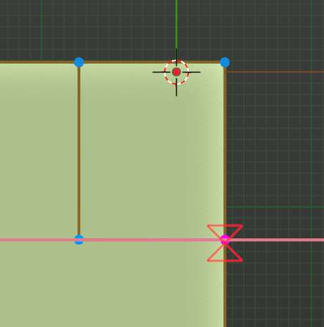
- Click on the new vertex to select it, then press G + G (vertex slide) and move your mouse so that the alignment symbol appears again (indicating that it will snap). Finally, finalise.
The two vertices were now merged into a single vertex, with its edges also connected. This will only happen if you have Auto Merge Vertices turned on, which is the button located above the XYZ cross in your viewport, next to the XYZ buttons, immediately after the Z button.
Now, the teacher didn’t have that one on, and therefore, he will move into what is called Vertex Merging, or from other 3D applications, known as Vertex Welding.
Wireframe Mode – Vertex Merging
So the wireframe mode in Blender is activated from the bar above the viewport, where you see these spheres. However, a faster way to activate wireframe mode is to use the hotkey Z, and then select Wireframe and/or switch back to Solid again.
Let’s continue…
- Drag a selection window around the two vertices, which in this case are overlapping.
- Right-click and select Merge Vertices (hotkey M) > By Distance, and then press Z to go back to Solid view mode.
The two vertices are now combined into a single vertex with its edge connected.
16 minutes into the video, the teacher will explain what you can use this for. Essentially, these are the methods you’ll use in Blender for typical architectural designs, but they are also commonly used for general 3D modelling and mesh editing. So yeah, he’s giving us a challenge. That’s up to you if you’d like to practice that on your own in Blender for now. He will continue to make some walls for a room after specific measures, so I suggest you watch the video from 16:00.
Through this video by Blender Academy and all that I have provided, I wish you great luck with your Blender projects. I’ll cover some additional useful topics here at AlfaMods later, featuring great Blender guides from YouTube content creators.